


The Internet of Things (IoT) is all about connecting devices and gathering information. In order to handle the sheer number of devices of typical industry 4.0 applications this needs to be fully automated. In this blog post we present a hands-on example how to monitor the electricity grid with an industrial Raspberry Pi single board computer that uses Modbus over Ethernet to connect to a Schneider PowerTag. All this is managed by qbee.io and the application logic is provided by Node-Red. Thus this can be automatically scaled to any number of devices.
We will show how qbee automatically installs a headless Node Red on a Compulab industrial Raspberry Pi and distributes the flow. The flow is templated such that the update frequency of the electricity measurement can be controlled through the qbee UI. This allows to control large groups of devices and to define different update rates for subgroups and different Schneider PowerTag installations. On 4G mobile networks it might be preferable to update every 30 seconds to save data costs while in a industry 4.0 enabled factory the electricity data needs to be monitored on a per second timescale.
We structure this use case into the following sections:
- Description of all system components (hardware and software)
- How to install and bootstrap qbee
- Headless automated Node-Red install or update
- Automated Node-Red flow roll-out across the fleet of devices
System Components
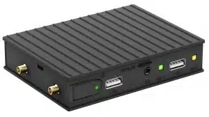
The embedded edge device – in this case an industrial RPI
We are using a Compulab industrial Raspberry Pi. This is an industrial RPI which has the great advantage that it runs from eMMC flash in addition to be designed for industrial use cases. This prevents SD-card flash corruption, it is much more rugged and different cellular and other options are available as well.
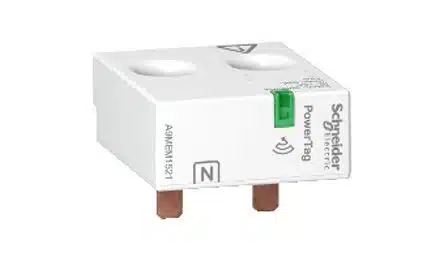
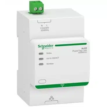
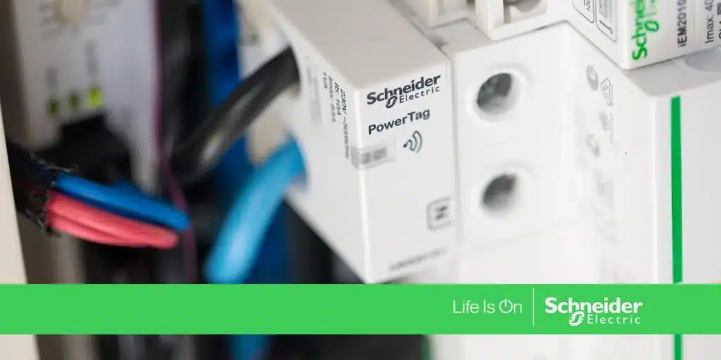
The Schneider PowerTag solution
Schneider offers a wireless power tag solution that allows to attach sensors directly on top of fuses or circuit breakers. A wireless receiver is capable of receiving multiple PowerTags and makes the data available through a Modbus over ethernet connection. The power tag and the Acti9 receiver can be seen below. The wires are passing through the PowerTAG which is powered by one phase.
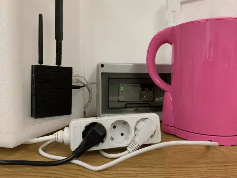
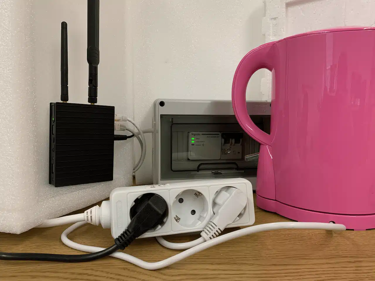
The complete demo installation
Below is an image of a very basic demo installation of the industrial Raspberry Pi connected to a network switch as well as to the Schneider PowerTag wireless link controller Acti9. The second ethernet port on the Raspberry Pi is used to connect to the Acti9 through Modbus over Ethernet / TCP. The Power tag is inside the white box (on top of the circuit breaker). In order to get a compact demo setup the Acti9 Link controller is placed on the same rail besides the circuit breaker. In real deployments this can be anywhere due to the wireless connectivity between PowerTag and Link controller. The electrical load (in this case a water kettle) is connected to the power outlet that comes from the circuit breaker. Thus the demo can measure any current / power flow consumed by consumers connected to the socket outlet.
The software
We are running the standard Debian Linux provided by the Compulab’s Raspberry Pi. This is fully Raspbian compatible. On top of this we use qbee.io to control the device remotely as well as Node-Red to do the communication with the Schneider Controller over Modbus reading all power and electricity values and transporting them further to a backend with MQTT. The whole stack is run fully automated and headless. This makes it possible to deploy this on many edge devices in production. Nevertheless, to prove that it really works we did a secure remote webserver login to show a screenshot of how Node-Red looks like on the edge device while the kettle was boiling the water (see image below). We can note a current of 8.3 Ampere and a power usage of 1849 Watts. Since a kettle is a pure resistive load we see a power factor of ca. 1 and 224 Volts. The purple “power” element with green “connected” is the MQTT output controller sending the data to the MQTT backend.
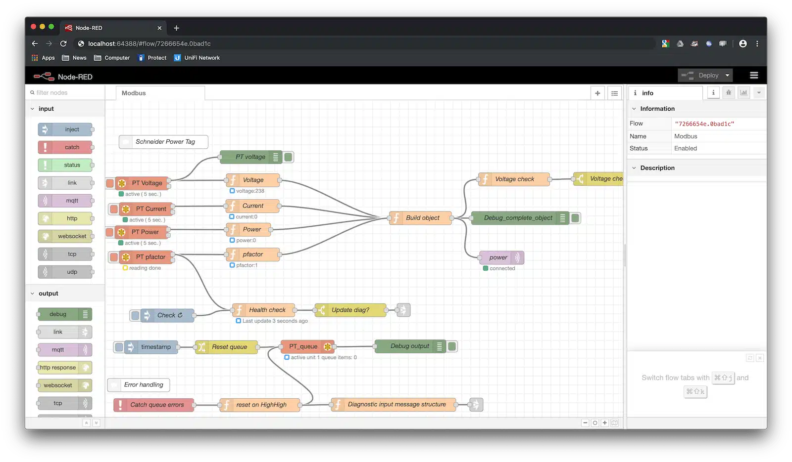
The above Modbus flow was originally developed by Csongor Varga and it is explained in this very nice video and available as a flow here. Thanks a lot. This was very helpful in adjusting the Node-Red flow for the Schneider Acti9 Modbus controller. This Modbus controller receives the Schneider PowerTag electricity information wirelessly. Our flow is available here.
How to install and bootstrap qbee
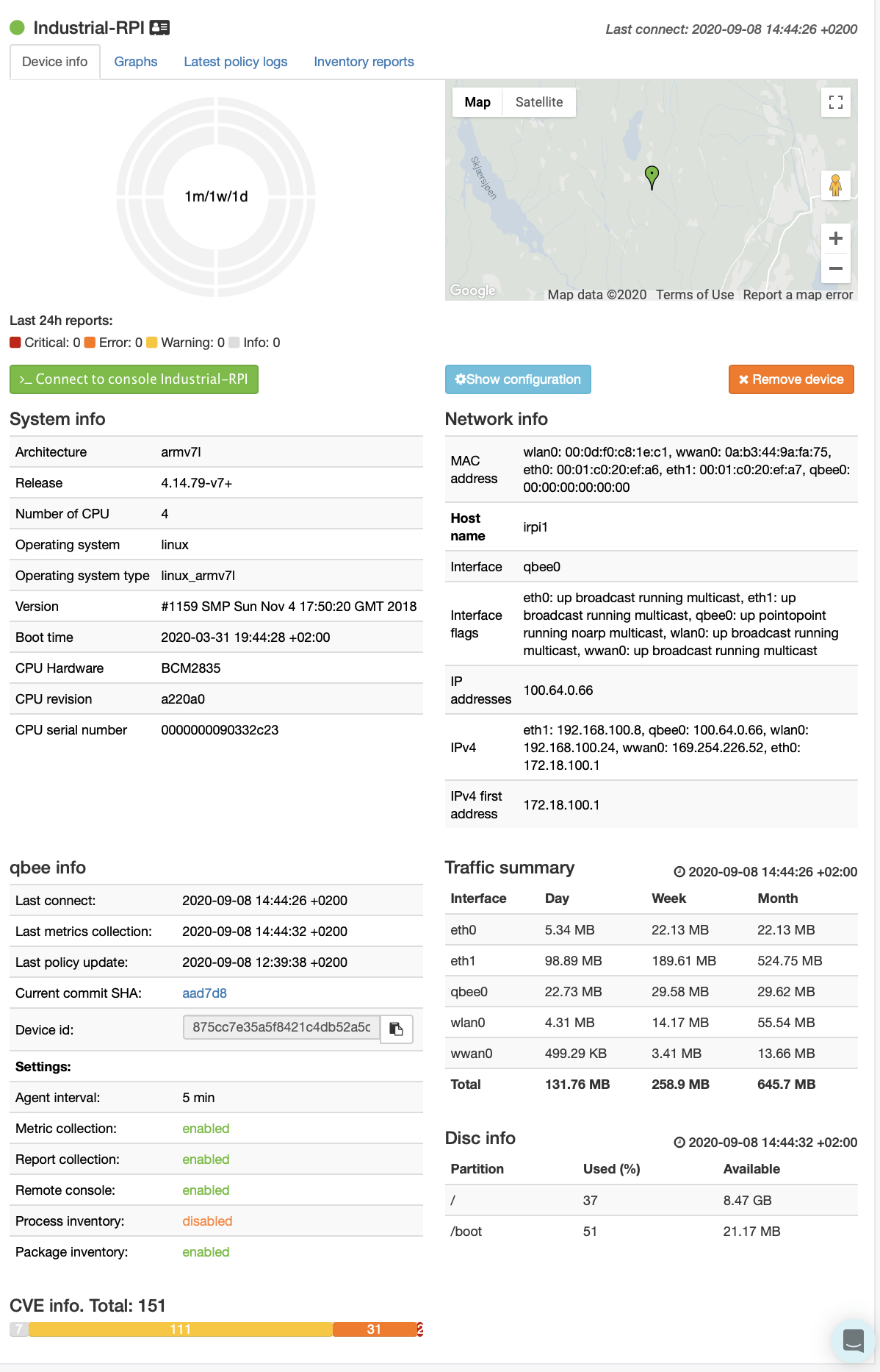
qbee is a device management and remote access tool for distributed embedded Linux systems. It allows to install and update software or the operating system through OTA software updates as well as to configure any aspect of a Linux system. It gives you built-in secure VPN access even behind complex network infrastructures and it is possible to remotely access a web server for example running the Node-Red desktop. For production systems we recommend to install the qbee agent already on the image. Then a script can securely bootstrap with a specific bootstrap key. This allows to associate the devices with a specific client or a specific group. Please see more about bootstrap keys and bootstrapping qbee here. When done properly the devices are available in the qbee UI:
Headless automated Node-Red install or update
It is possible to install and/or update Node-Red fully remotely through qbee. This is done fully headless. We have made a tutorial how to do this. It is also possible to add specific modules that are needed. In our case this is the Modbus package which we use in the latest version. If you have a working install of Node-Red already you can skip this step but it is recommended to not rely on the standard package as described here.
Automated Node-Red flow roll-out across the fleet of devices
The main point of this tutorial is to roll out a Node-Red flow fully automated including provided credentials for login into services such as MQTT or databases such as Influxdb or similar. We have a very detailed description how to do this in the tutorial here. But we will go through the main steps in this tutorial as well. On your development system you need to ensure the following in your Node-Red user folder (usually the hidden folder “node-red” in your user directory):
– the .config.json should not contain a key in the last section below “user”. Otherwise everything gets encrypted with that key and not the defined credential secret below. This can cause serious headaches. For more information please follow the tutorial link above.
– in the settings.js file you needs to uncomment //flowFile: 'flows.json',and define your credentials for encrypting the MQTT information by uncommenting and defining credentialSecret: "my-personal-secret-key",
Then you can restart Node-Red and the credentials get active. Open the editor, and copy the Modbus flow from here. Define your MQTT settings in the MQTT block and deploy the flow. This causes the flows.json to be written as well as that the credential file flows_cred.json gets created/updated.
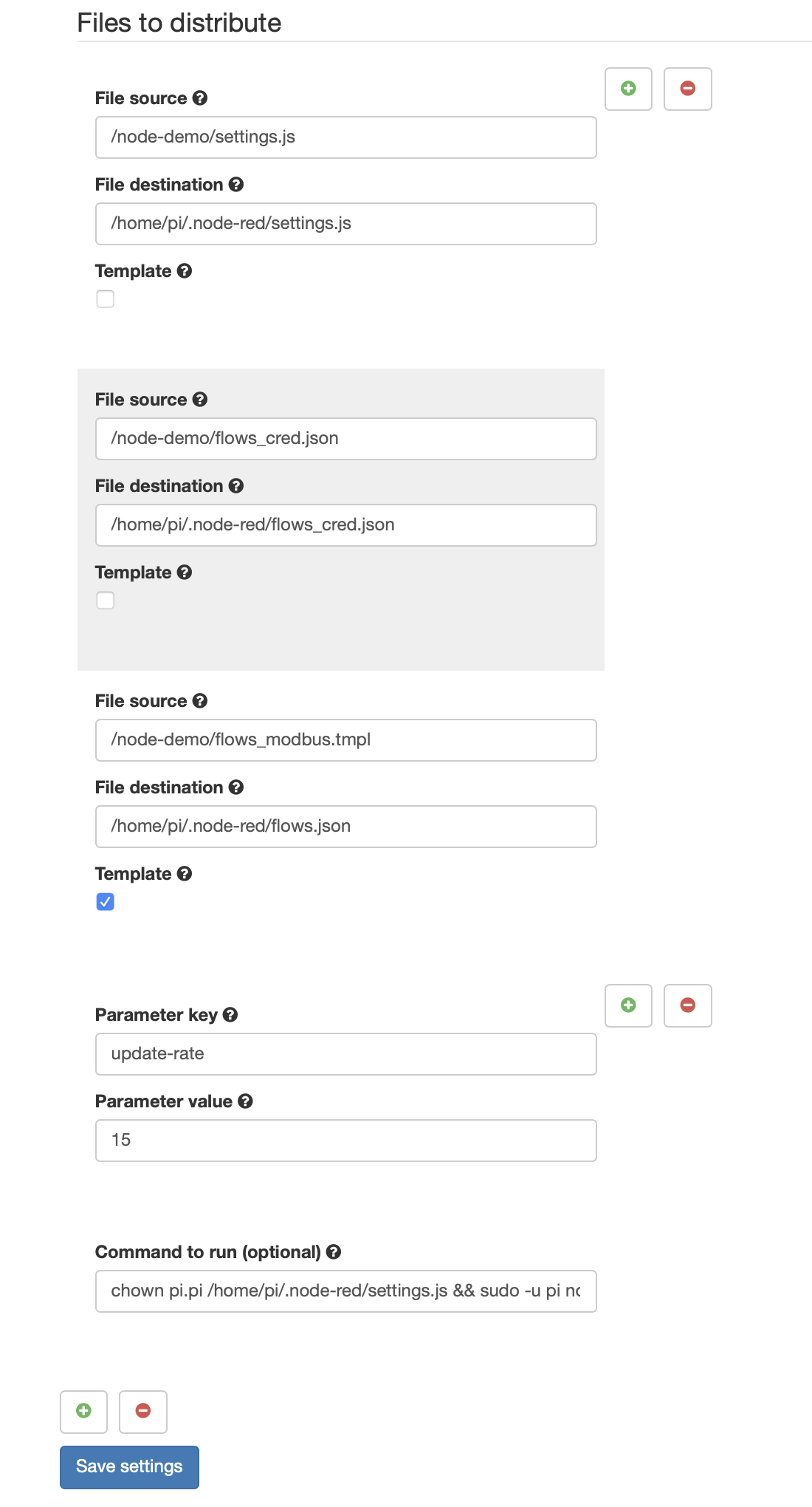
Now you can upload the settings.js, the flows.json and the flows_cred.json files to the qbee file manager. Then you go into ->Configure and select your device or group of devices. Under ->System->File Distribution you can define which files should get distributed and where they should go (obviously your node-red directory) as well as a final “command to run” to restart the application again. This command changes the ownership of the settings.js file to your user that runs Node-Red and then Node-Red gets restarted. “chown pi.pi file” changes both user and group ownership at once. This is important as settings.js is only read if it has the same ownership as the user running Node-Red.chown pi.pi /home/pi/.node-red/settings.js && sudo -u pi node-red-restart
In this demo we play out the previously mentioned files with one small difference. We want to introduce key-value templating into the flow. This allows to dynamically change flow values such as strings, numbers or anything else through the qbee user interface. Therefore we do not use our flows_modbus.json but instead create a template file called flows_modbus.tmpl. The easiest way to do this is to go into the json flow with an editor and there you replace the "rate": "15", with "rate": "{{update-rate}}", in the modbus-read controllers. This mustache notation makes “update-rate” available as a key-value pair in qbee. Then you save the file as flows.tmpl and you have your template file. You can expose anything you want and use as many key-value pairs as necessary. More information about this can be found in the deploy and configure Node-Red tutorial. The next step is to check the template checkbox and introduce an “update-rate” in the key-value parameters in the qbee UI. This will expand the template file into a correct .json flow replacing the {{update-rate}} mustache noted variable with a real number in this case “15” for 15 seconds. Please see the image below.
Any time the key value pair is changed, this change is then saved and committed Node-Red will automatically restart and load the flow with the new values. The qbee agent expands the template on the device into the flow file. If there is a new value coming from the UI it changes the file and initiates the restart. Through the file distribution configuration it is possible to define different key-value pairs to different devices or group of devices. This will then change the frequency with which the Schneider PowerTag will be queried.
In order to proof this we replace the update-rate with 10 seconds and save and commit that.
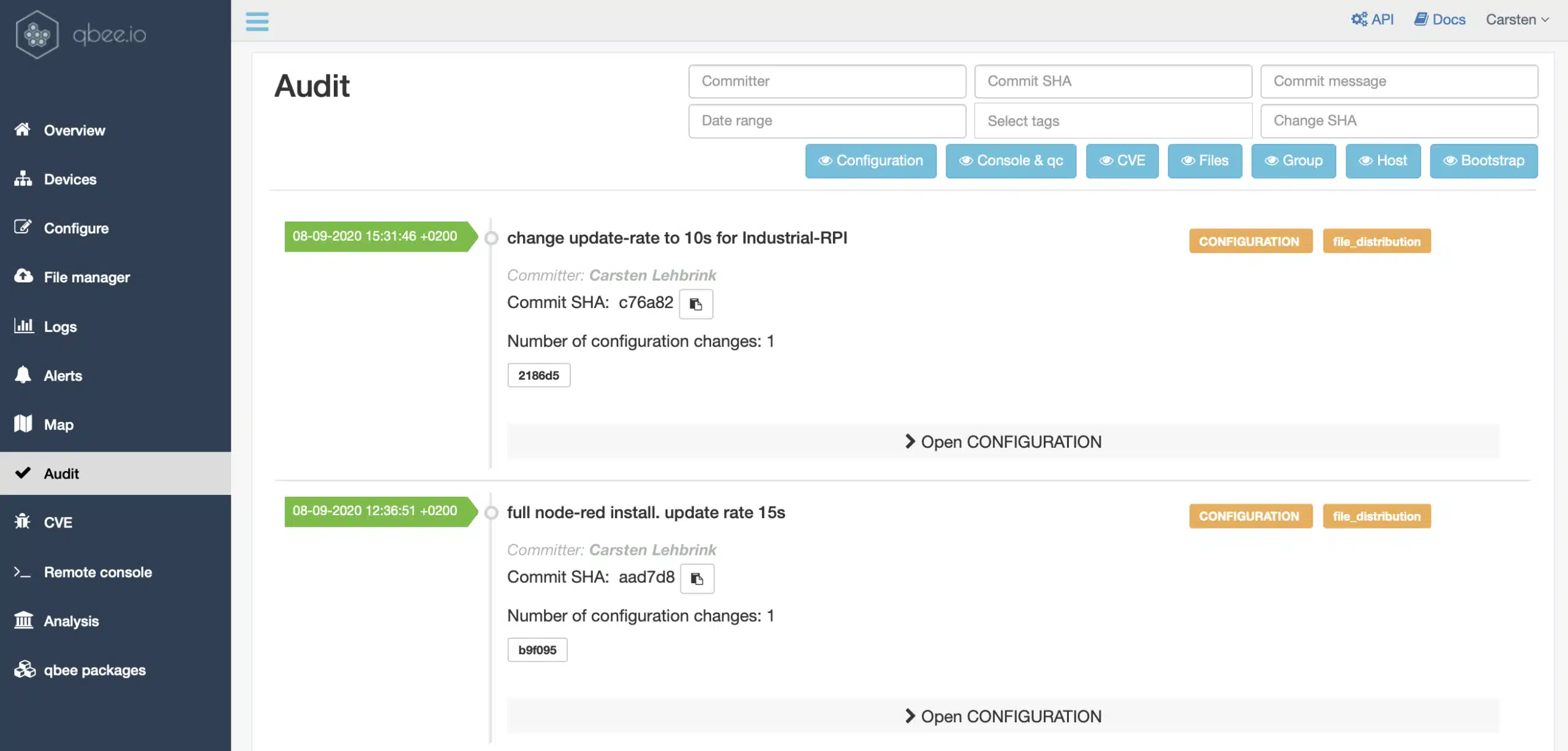
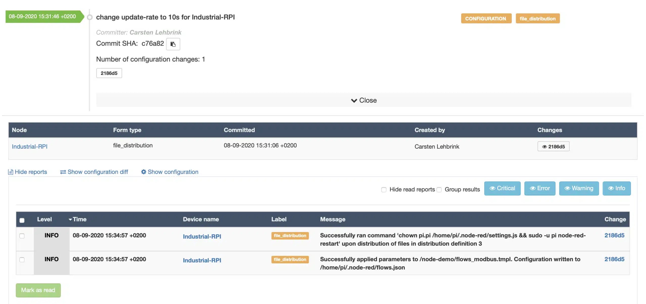
Now we can wait for this to be distributed. Eventually we will get a log message that this has been done.
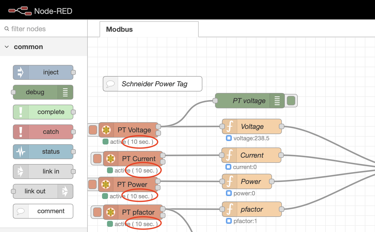
Then we can use the qbee remote access to access the remote Node-Red installation on the embedded Linux edge device. We have a tutorial how to do this with our qbee-connect tool here.
It is clearly visible that the update rate has been adjusted to 10 seconds for all 4 modbus-read controllers. Thefore, the Schneider PowerTag is polled every 10 seconds.
Conclusion:
We have shown that qbee can do a complete headless Node-Red installation including all necessary modules that are needed and providing credentials for elements that need those. It is also possible to update Node-Red or the modules. Then a standard flow can be distributed to a large number of devices in production including the credential settings. It is possible to distribute different flows to different devices or group of devices. When using flows it can sometimes be practical to be able to change some parameters for some devices. This is possible through templating thus creating an extremely flexible solution to run and maintain Node-Red in production. This allows to build a fully automated electricity monitoring solution with ModBus and Schneider PowerTag components.
If you are interested in additional information please feel free to reach out to us. You can also register for your free 30 day trial of qbee.io.